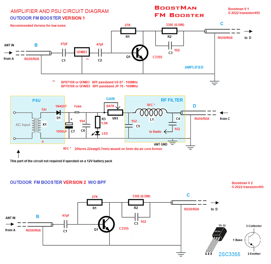
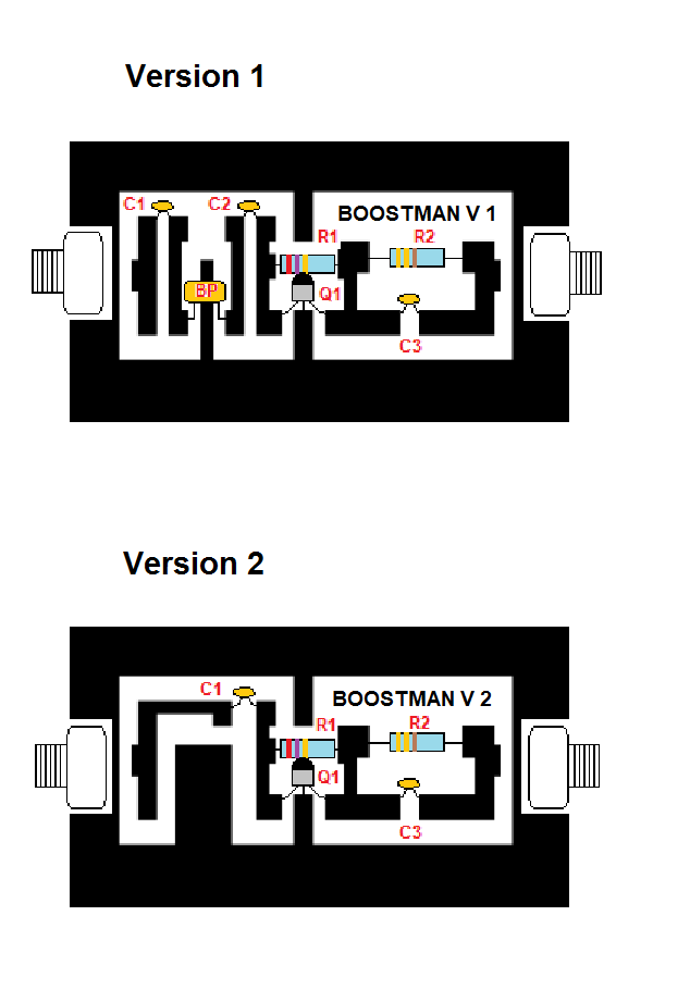
Fig.1 Schematic of FM booster
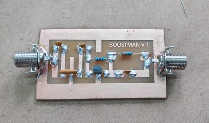
BoostMan - A High Performance Outdoor FM Booster |
I've started working on an FM signal booster since there have been many interests noticed recently for a working VHF FM booster which can amplify weak or distant signals(or even those locals which appears hesitant to enter your home/building and mark a presence on your tuner/radio).
I've worked on few designs -both indoor and outdoor type amplifiers, and this one seems to be working great and promotable considering it's simplicity and easy to make, offering great reception.
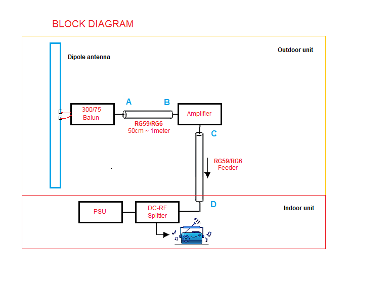
BoostMan followed good old terrestrial analog Television booster architecture having a dipole antenna attached at top-mast to the booster amplifier and an indoor PSU cum gain control unit. 75ohms feed cable like RG59/RG6 is used as feeder cable.
Fig.1 Schematic of FM booster
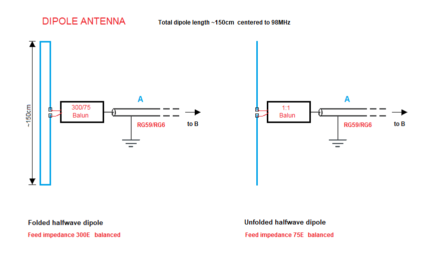
WIth a homemade folded dipole antenna, I could receive 30+ local and distant FM radio signals across the state and nearby states, ie, hundreds of kms away. DXing is very nice to witness, especially when the signal comes in and engage the stereo decoder for a short time and then fade away or just be there jumping in/out. It's a pleasure to watch it on the tuner operation indicators. Signal presence, Signal strength, Stereo, VU -all will dance during a DX window!
R1 - 27K 1/4w, metal film resistor
R2 - 330E 1/2w, metal film resistor
R3 - 1.5K 1/4w, metal film resistor
VR1 - B47K, linear potentiometer with knob and mounting nut
Q1 - 2SC3355/2SC2570 Genuine NEC/RENESAS/UTC Transistor
C1/C2 - 47pF ceramic disc
C3/C4/C5 - 0.001uF/102P ceramic disc
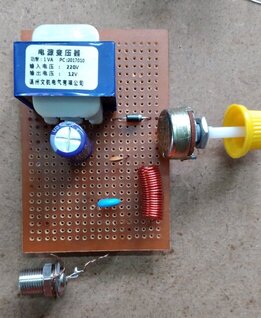
X1 - 0-12V Step down transformer 100mA. A 500mA output transformer can be used instead.
B1 - 250mA fuse
D1 - 1N4007 rectifier
L1 - 20 turns of 22SWG[0.7mm] enamelled copper wire closely wound on a 5mm former, air core
BP87108 or GFMB3 wideband BPF [only for Version 1 circuit]
RG59/RG6 75ohm coax -length as per required, F-type/BNC coax connector
Printable PCB layout of Version 2 circuit can be downloaded here
|
|
Email: transistor495@gmail.com